
Description
This is an open source / open hardware project that I developed with my son (who was 11 years old at that time) for internal use for automating some of the tedious and repetitive tasks that we do around here.
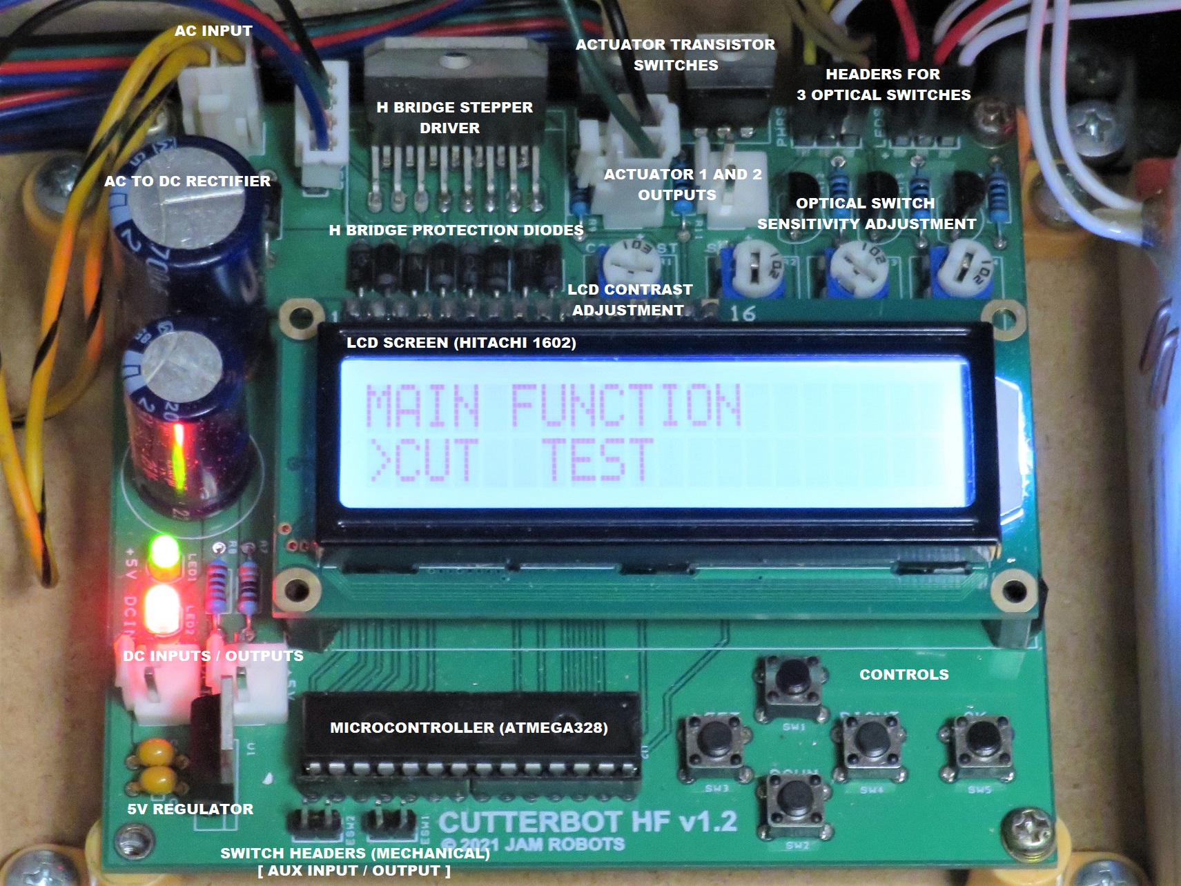
In a nutshell, this is fully integrated, all in one, easy to assemble, basic robot controller for tasks like automated cutting, bending and crimping.
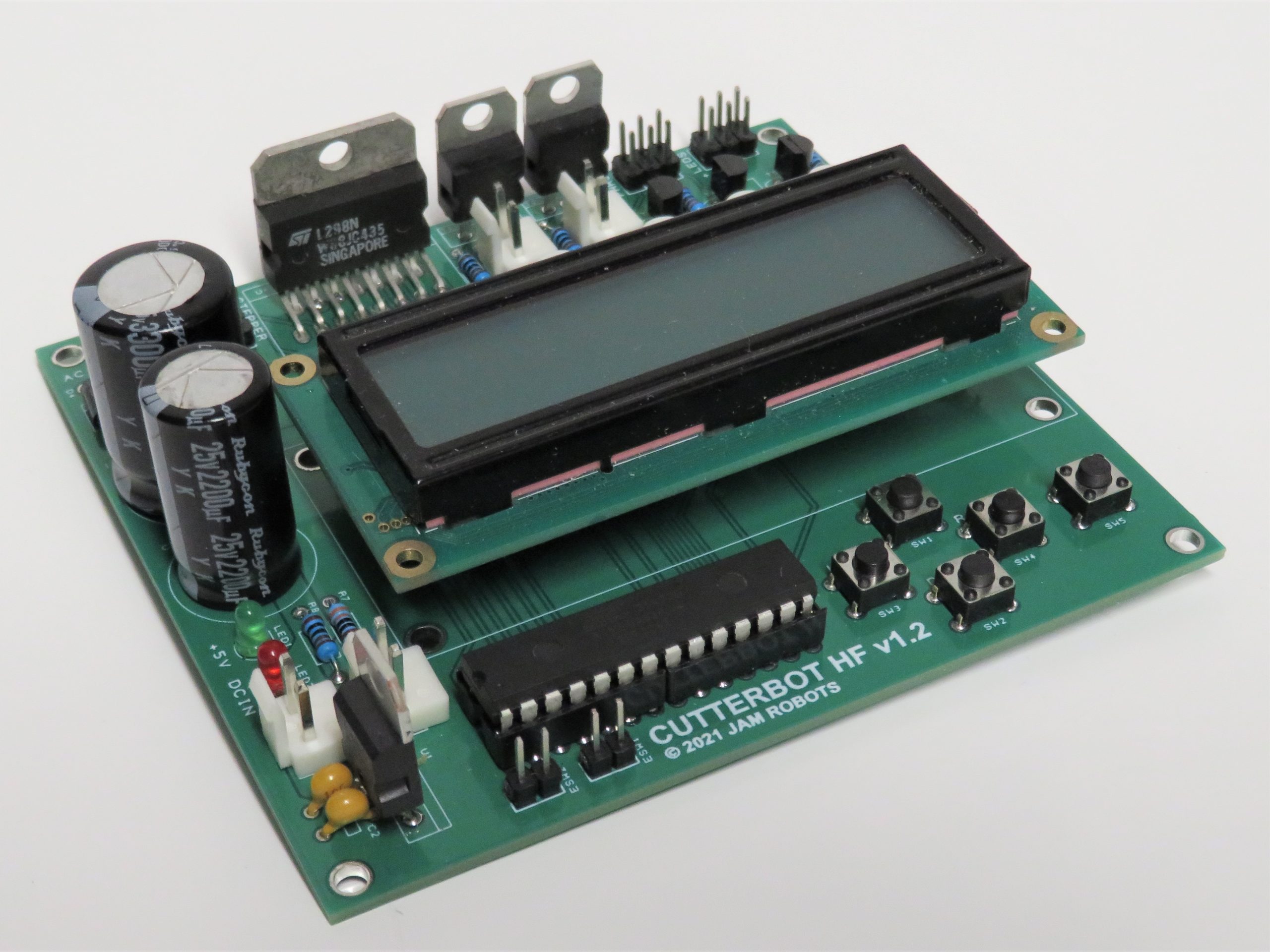
This project is based on very basic electronics concepts and simple Arduino code, but functional enough that makes it actually useful for a variety of tasks that require precision movement along one axis, and the ability to control two other tasks. The board has an H-bridge driver for controlling a stepper motor, two high power transistor actuator switches, three optical sensors (simple LED + photoresistor combination), and two other additional auxiliary input / output headers.
The board was initially developed as an integrated controller for a cutting machine, hence the name CutterBot, but as we will see later, can be easily repurposed for other variety of tasks.
Schematics
Here’s the annotated CutterBot schematic.
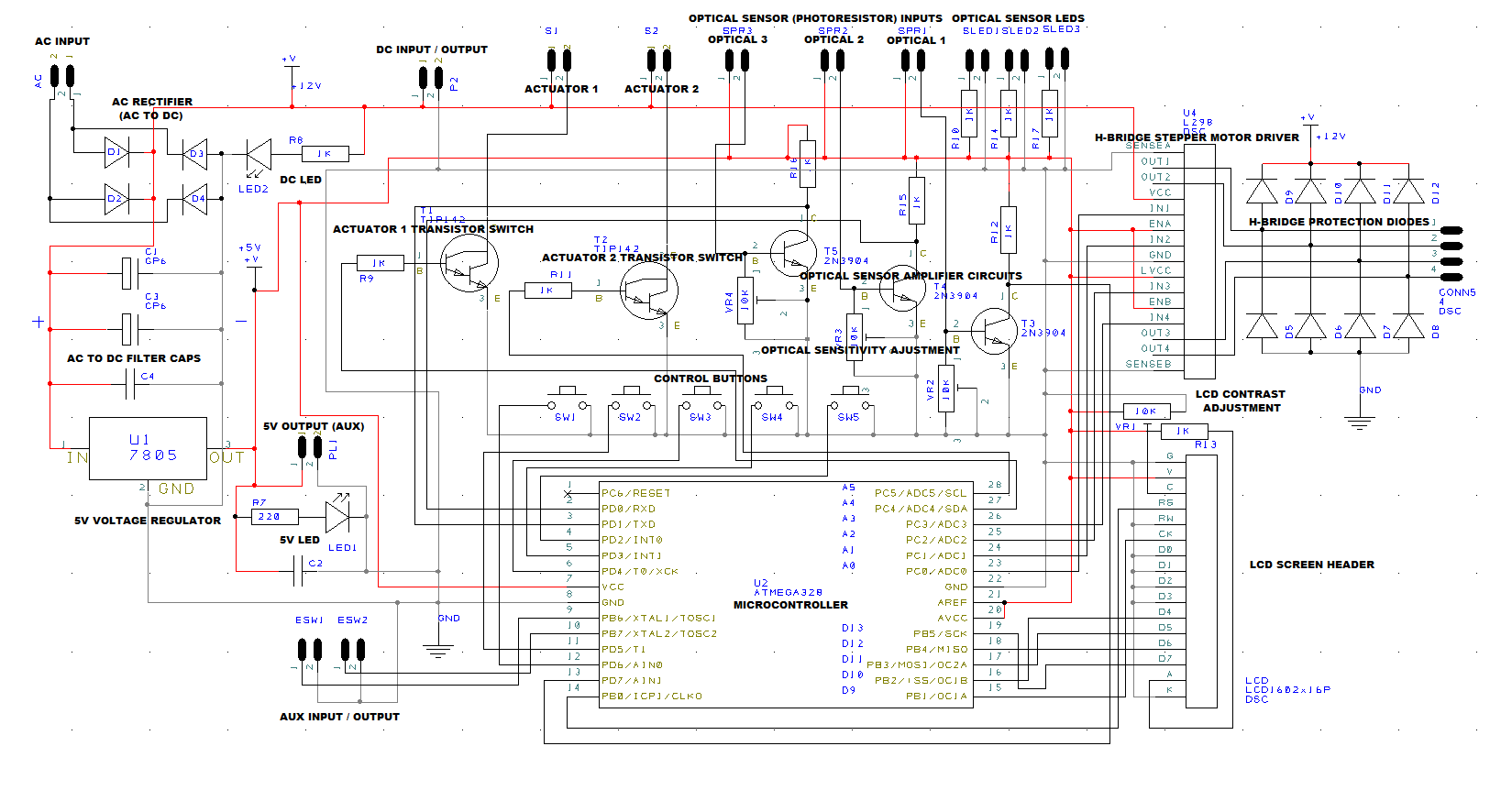
Here is the PDF version of the raw schematics.
Gerber Files
Download this zip file to manufacture your own boards.
Code
This is where all the logic for your machine will need to go. Provided as part of this project is the code for the cutting robot (other variants coming soon).
In order to use this code on the CutterBot controller, you will need to do the following:
- Download the code.
- Open the Arduino development environment on your PC.
- Use a fresh ATMega328 (the 28 pin DIP version) without a bootloader.
- Burn AVRDude’s Minicore bootloader to enable the internal 8MHz oscillator on the ATMega328.
- Use a serial programmer (with Arduino as ISP) to load the program into the microcontroller.
- Modify as needed.
Configuration
If you want to implement a similar cutting tool using the existing code with minimal / no changes, you’ll need to connect the sensors / peripherals in the following manner:
The cutting device connects to ACTUATOR 1. This can be any type of single direction actuator including a motor, coil, laser, a solenoid or a relay controlling another high power device. The output voltage from the ACTUATOR plug is whatever is fed into the ACIN or DCIN / OUT plugs on the controller board.
ACTUATOR 2 is not in use in this code.
SENSOR 1 (OPTICAL) has to be connected to a photoresistor which along with an LED, can detect a resting (non-cutting) position of the cutting device. The code will power the actuator until this position is detected before starting the cutting action. The default cutting action is assumed to be in-progress if occlusion of light is detected by this sensor. Adjust the sensor sensitivity until reliable operation is achieved.
SENSOR 2 (OPTICAL) has to be connected to a material detector in the FEEDER. If the sensor doesn’t detect light, material for cutting is assumed to be present and cutting operation can proceed.
SENSOR 3 (OPTICAL) connects to the a photoresistor detector that is behind the cutting device. Blocked light is assumed to have material present and is required before a cut is made. If the condition doesn’t change the cutter attempts the action again at which point is will require the condition of this sensor to change. If this fails, the logic assumes that there is a material jam.
The STEPPER MOTOR connects to a stepper motor and a device that is capable of using a FEEDER to move the material into the cutting device. During the current cutting logic loop, the FEEDER only moves the material forward, although reversing it is possible in the test menus.
Operation
When powered on, the controller will provide two selections:
- CUT – A submenu for activating the cutting function. You will be asked for length of material to cut (see code for how length is calculated) and number of pieces to cut. The cutting operation will then begin. See the section above to see what the controller will expect in terms of sensor conditions and how power will be activated in the FEEDER and the cutting ACTUATOR.
- TEST – A sub menu to check the status of the sensors, buttons, actuators and steppers. The TEST screen consists of input test and output test submenus:
- INPUT – Check status of buttons, optical and mechanical switches.
- OUTPUT – Send power to actuators and move the stepper motor forwards and backwards. This screen will also show optical sensor status for easy adjustments of the machine.
Pressing the OK button enters and exist the menu. Pressing UP on the directional button goes back the the previous menu.
The code and the hardware provided here is free of change but without any warranty whatsoever. It will be up to you to work with what is provided and change as required to implement the robot of your dreams.
I will provide as much documentation as possible (within reason) and may provide limited assistance with your project and feature requests depending on time availability.
Specifications / Parts
- Board Size: 100mm x 80mm
- Power: DC IN: 12-24V, AC IN 12-24V
- Stepper Motor: 5 wire either 12V or 24V 2A Maximum (depending on supply)
- Stepper H-Bridge driver: LM298N
- Actuator: Motor, Coil, or other inductive or resistive load 5A maximum, supply voltage
- Actuator Driver: TIP142 NPN Darlington transistors
- Optical Sensors: 10K standard photoresistor
- Optical Amp: 2n3904 NPN transistors
- LCD: Hitachi compatible type 1602 (16 characters, 2 lines)
- Microcontroller: ATMega328
- Voltage Regulator: 7805
- Diodes: All 4007.
Revision History:
Rev 1.0: Initial Prototype.
Rev 1.1: Fixes some issues with bugs in the prototype PCB.
Rev 1.2: Added additional actuator for future implementation and 2 more optical sensors for improved jam detections.