I have to fix a number of my PCBs. Some that are currently broken, I need for my JAMMA adapter project. It’s been holding things up more that I like.
While I’ve been working on these I decided to spend a day on creating various stickers for RAM, ROM and CPUs that can be stuck on the chip and will list label each pin for easy probing.
I managed to whip this out quick. I works but maybe an online repository with a number of these that people can use is the way to go. I may consider it when I have some free time.
In the mean time, this code Python code takes in your pin list, the chip size and your printer DPI settings and generates an image of the correct size that can be printed on a label printer.
from PIL import Image, ImageDraw, ImageFont
import os
class ICPins:
def __init__(self, name, pins, package):
self.name = name
self.pins = pins
self.package = package
# DIP body widths are .25" (standard) and .5" (wide)
self.width = .5
# DIP leg spacing is .1"
self.pinspacing = .1
self.padx = 5
self.pady = 5
self.dpi = 300
self.fontsize = 12
def to_img(self):
filename = self.name + ".png"
# calculate sizes based on input and DPI
y = self.pady
x = self.padx
if (self.package == "DIP"):
pinspacing = int(self.pinspacing * self.dpi)
width = int(self.width * self.dpi)
#fontsize = int(self.pinspacing * 72) - 1
fontsize = self.fontsize
sizex = width + (self.padx * 2)
sizey = int((len(self.pins) * pinspacing) // 2 + self.pady * 2)
fnt = ImageFont.truetype('arial.ttf', fontsize)
print(sizex, sizey, pinspacing, fontsize, fnt.getsize('A')[0], fnt.getsize('A')[1])
# create image
image = Image.new(mode = "RGB", size = (sizex, sizey), color = "white")
draw = ImageDraw.Draw(image)
# draw pins
leftpins = self.pins[:len(self.pins)//2]
rightpins = self.pins[len(self.pins)//2:]
for pin in leftpins:
draw.text((x,y), pin, font=fnt, fill=(0,0,0))
y = y + pinspacing
x = x + width
y = y - pinspacing
for pin in rightpins:
w, h = fnt.getsize(pin)
draw.text((x - w - self.padx, y), pin, font=fnt, fill=(0,0,0))
y = y - pinspacing
shape = [(0, 0), (sizex - 1, sizey - 1)]
draw.rectangle(shape, outline = "black")
# save file
image.save(filename)
# show file
os.system(filename)
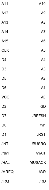
pins = ["A11", "A12", "A13", "A14", "A15", "CLK", "D4", "D3", "D5", "D6", "VCC", "D2", "D7", "D0", "D1", "/INT", "/NMI", "/HALT", "/MREQ", "/IRQ", "/RD", "/WR", "/BUSACK", "/WAIT", "/BUSRQ", "/RST", "/M1", "/REFSH", "GD", "A0", "A1", "A2", "A3", "A4", "A5", "A6", "A7", "A8", "A9", "A10"]
ic = ICPins("Z80", pins, "DIP")
ic.to_img()
Here’s an image that was generated from the above Z80 definition.
I hope this can come in handy to someone. If you would like to see this as a web tool, let me know and I can probably make this a repository of pinouts for the common ICs and maybe even allow you to add and create your own stickers.