
Generating video with a simple micro can be a headache. I’m going to skip all the life lessons here and get down to business right away.
Do’s and Don’ts
In order to generate video on a cheap micro controller, you must:
- Have a microcontroller that supports an external clock crystal or oscillator. Internal low precision oscillators will not sync, or if they do, you will have a wobbly image that may periodically lose sync. Precision to 1% of timing is often required, but it depends on the monitor in the end.
- Have a fast enough micro to process all the pixels you want to display within the time it takes the raster scan one line. A 16MHz micro will probably do ok with 15KHz scanline (240 active lines), but you will not likely be able to do more than 20 horizontal pixels on it. The higher the scanline frequency the worst this problem gets. On a 16MHz micro at 31.5KHz you will only be able to get around 10 horizontal pixels. This is with optimized code that does nothing more than to switch the raster off and on in a tight loop.
- Put all your code in the timer ISR. This may sound like the wrong thing to do, but you need to have total control of where processing happens. You want to do your house keeping inside blanked out areas or during vertical retrace. If you don’t, troubleshooting may be a pain, as one timing overrun inside a main loop will cause the whole thing from syncing.
- Sleep and wake up on Timer interrupt. When you put the micro to sleep and wake it up in timer event, it will take the same amount of time to enter the ISR. If you don’t sleep, the micro will have to complete the current instruction before it jumps to the ISR and that may vary by instruction being executed, causing a wobble in the display.
Before jumping into the code, lets talk about the screen real estate and what we need to know in order to generate an image.
Screen Real Estate
This is a standard timing and screen region diagram for VGA resolution of 640×480 at 60 Hz. Note that the 640×480 is only the visible or active area of the screen.
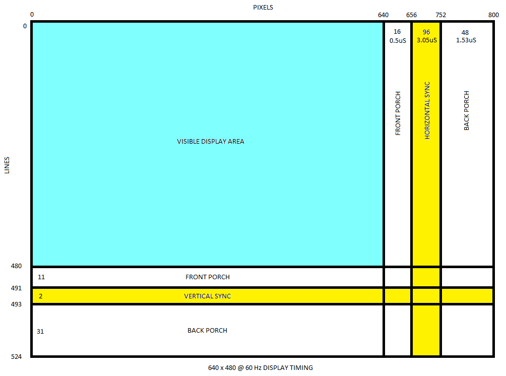
Let’s go over all the important bits.
- The horizontal and vertical timing pulse must begin at the correct interval. This is the most critical thing your code must be able to do. It does not matter whether anything else works or not if you can’t get your display to sync to the image. With a slow micro it’s going to be impossible to work on a pixel by pixel level, so you will have to set your timer to tick on the horizontal line frequency (31.5 KHz for 640×480, 15.7KHz for 320×240, etc…)
- The width or the sync pulse is less critical. It should be possible to get away with some inaccuracy here as long as the pulse width is not too short. I find that doubling the horizontal pulse or giving the vertical an extra line doesn’t cause any issues.
- You must turn off the raster during the porch regions and when syncing. This is to get the black levels correct on older displays. Failing to do so will result in a black screen, washed out colors or color problems.
- Horizontal resolution isn’t at all important unless you are working with a pixel clock. Pixel rates are 24MHz or a 640×480 mode which is faster than your micro controller clock. You can have a horizontal resolution of a few dozen pixels if you optimize your code, but won’t be able to approach anything near the intended resolution. Your monitor will not care if you switch the raster mid-pixel.
- Vertical resolution is important. You must stick to what is in the specification. It’s possible to add or remove a line or two or increase timing somewhat at the expense of vertical resolution and / or frame rate, but the monitor will expect a steady horizontal sync pulse that’s close to the intended rate for the mode you are trying to use.
- As the raster moves left to right, drawing horizontal lines, and top to bottom as lines are added below, you will time and turn on and off the RGB inputs in a way that will display an image. It’s possible to create a crude character display or image viewer by rotating character mask bits in a timely manner and depending on whether the current bit is set, turning the raster on or off accordingly. This will likely require the preparation of the bit stream in advance, during a period when lines are outside the active region. Images can be handled in a similar manner.
- To increase processing time, it’s recommended to reduce the visible area even more, and use the time outside the active window for additional processing. In fact, with the short time available for horizontal front and back porch, it’s usually necessary to exit the timer interrupt before the active area is fully drawn, as exiting the ISR and putting the micro to sleep make take too long and may overrun the timer and loss of sync.
- It’s irrelevant whether you deal with the active area first in the ISR, or start at either porches or sync signal. I usually begin with the horizontal sync pulse upon entering the ISR to make sure the sync timing is 100% consistent.
Color and Sync Signals
Now a word or two on the signal and sync levels. Sync can be either separate horizontal or vertical signals, or a combined sync. Combined sync (sometimes called composite sync) is usually the result of horizontal and vertical syncs XORed together, but the display may be perfectly fine with the sync ANDed or ORed together as well.
Sync levels can either be positive (logic high on pulse) or negative (logic low on pulse).
The digram here shows a set of separate and combined negative sync signals.
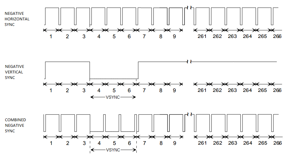
Sync signal levels are typically negative 1Vpk-pk for VGA or TV type monitors or 3-5Vpk-pk for an arcade monitor.
The color intensity levels are 0.7pk-pk for VGA and TVs and 3-5V pk-pk for arcade monitors. This is for RGB signals. YUV / component, composite and SVideo combine color information into an encoded signal that also includes sync. This requires a separate overview as there is a lot of information to cover.
Pseudo Code
Ok, with all that out of the way, here’s some pseudo code from a MSP430 template that I have developed for my projects:
// screen definitions
static int vid_vsync_start_line;
static int vid_vsync_end_line;
static int vid_visible_line_start;
static int vid_visible_line_end;
static int vid_last_line;
static int vid_end_line;
static int vid_num_fields;
void set_240p_mode(){
vid_visible_line_start = 3;
vid_visible_line_end = 237; // 240 visible
vid_vsync_start_line = 244; // 10 lines front porch
vid_vsync_end_line = 247; // 3 lines vsync
vid_last_line = 262;
vid_end_line = vid_last_line + 1;
// 15.7KHz = 1018, 31.5KHz = 509 at 16 ticks per uS
TIMER_ISR_TICKS = 1018;
mode_idx = VID_MODE_240P;
}
void main(void){
watchdogOff() // Stop WDT
// make sure power is stable before initializing hardware
init();
set_240p_mode();
setTimerInterrupt(timerISR)
while(1){
// Enter low power sleep w/interrupt
// timer isr will wake up mcusleepMCU(powerlevel)
}
}
interrupt void TimerISR(void){
static int line = 0;
// screen anatomy (lines / frame)
//
// +--------------------+ line 0
// | |
// +--------------------+ vid_visible_line_start
// | |
// | visible region |
// | |
// +--------------------+ vid_visible_line_end
// | front porch |
// +--------------------+ vid_vsync_start_line
// | sync |
// +--------------------+ vid_vsync_end_line
// | back porch |
// +--------------------+ vid_total_lines
// line anatomy
// +------------------------+-------------+------+------------+
// + visible region | front porch | sync | back porch |
// +------------------------+-------------+------+------------+
// start the line at the sync pulse for accurate timing
// front porch can be ignored - we start line scanning at HSYNC
// back porch can be ignored too - can be used for housekeeping
// turn off video - should be done at the end of the scanline
OUTPORT = VID_BLACKPIXEL;
line++;
// horizontal sync pulse on every line
// we xor (toggle) sync to combine hsync and vsync into csync
OUTPORT ^= VID_PIN_SYNC;
delay_cycles(VID_HSYNC_CYCLES);
OUTPORT ^= VID_PIN_SYNC;
// vertical sync start
if (line == vid_vsync_start_line){
OUTPORT ^= VID_PIN_SYNC;
}
// vertical sync end
else if (line == vid_vsync_end_line){
OUTPORT ^= VID_PIN_SYNC;
}
// last line
else if (line == vid_end_line){
line = 0;// reset sync to normal(high for negative sync)OUTPORT |= VID_PIN_SYNC;// do all your housekeeping// in back porch or blanked areas// debounce buttons// change screen contents// manage peripherals// any other logic
}
// visible lines
elseif (line >= vid_visible_line_start && line <= vid_visible_line_end){// dislay checkerboard gridif (mode = MODE_GRID){while (cellnum){OUTPORT = cellcolor;cellcolor ^= VID_PIN_CELL_COLOR;cellnum--;}OUTPORT = VID_PIN_BLACKPIXEL;cellnum = vid_grid_cells;}// solid screenelse if (mode == MODE_SOLID){OUTPORT = VID_PIN_SCREEN_COLOR;delay_cycles(VID_HOR_LINE_CYCLES);OUTPORT = VID_PIN_BLACKPIXEL}}}
Progressive vs Interlaced
Progressive video is straightforward since every frame is the same and is generated the exact same way.
Interlaced video has two fields of lines that interlace each other. While the fields can be considered two separate frames, and can be made identical, the fields are not typically generated the same way.
As an example the standard 480i TV video is made up of two fields each one being 262.5 lines, for a frame total of 525 lines.
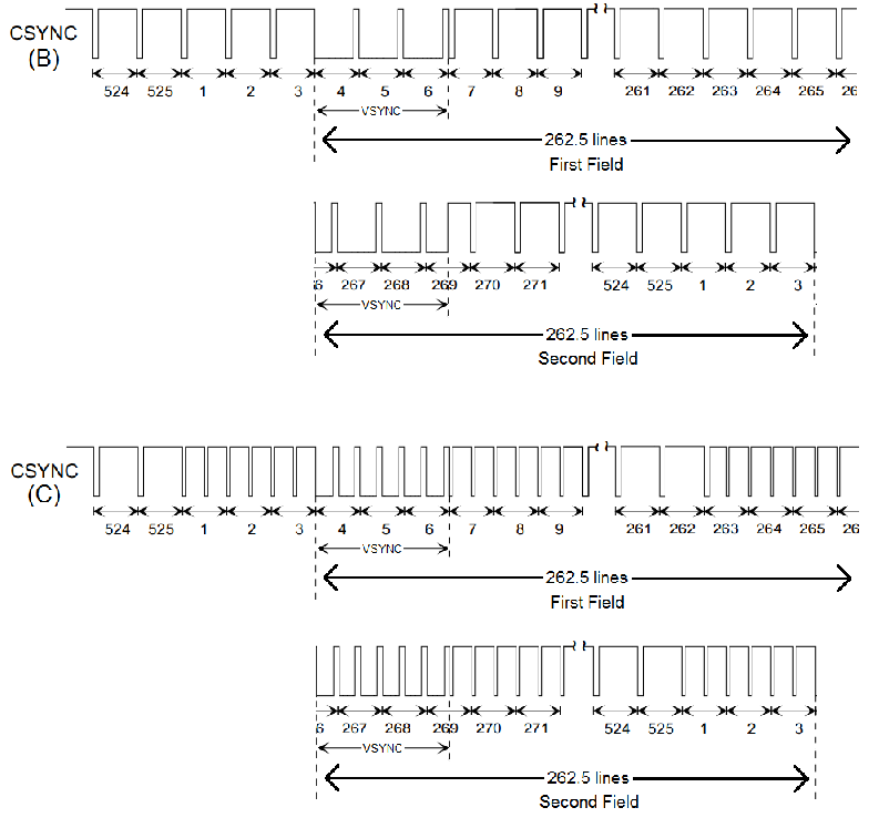
(C) standard sync for interlaced 480i
So how does one generate a interlaced signal that is 262.5 lines? The easy answer is that we treat each frame the same, giving both 262 lines, but shift the vertical sync signal half a line forward at the end of the second field. We also must add one line to the first field so that the total line count adds up to 525.
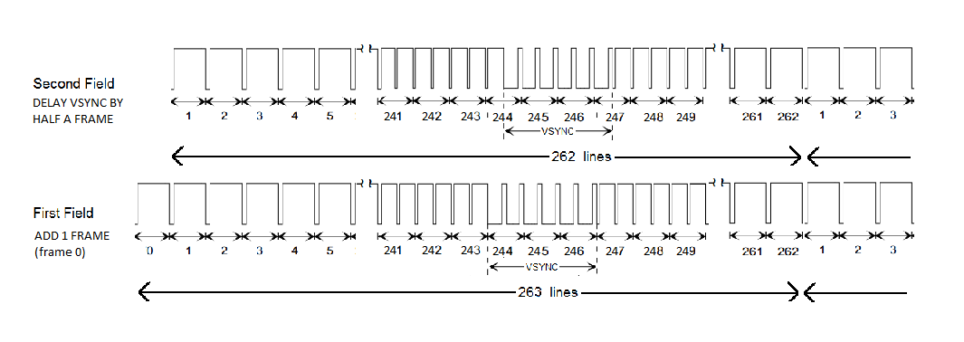
It may be difficult to see this in the above diagram, but the first field starts off with line 0 while the second starts off with 1, and at frame 244 we push the start of the vertical sync component by half a line forward. This allows for an easy and straightforward production of interlaced TV video signals on a micro controller.