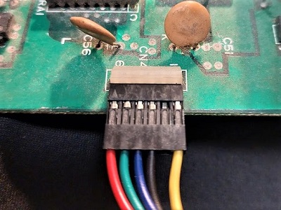
Video Connector
The connector is a simple 6 pin header with .1″ (2.54mm) spacing. It should be connected to the board as follows:
Power Connector
Now, here’s the correct way to connect the 3 power connectors. This corresponds to the the following pinout table for this connector:
| PIN | FUNCTION |
|---|---|
| 1 | +5V |
| 2 | +5V |
| 3 | +12V |
| 4 | -5V |
| 5 | GND |
| GAP | |
| 6 | GND |
Your connection should look like follows. Note the position and the order of the yellow (+12V) and the blue (-5V) wires.
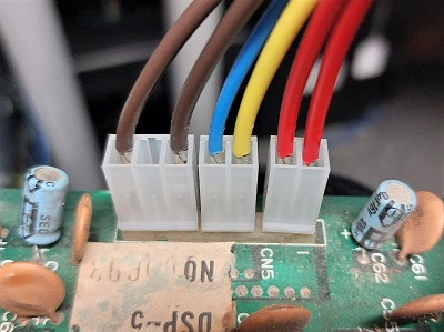
Please ensure the plugs are connected in the proper order or damage to you board may occur.