
There are a number of good SONY CRT television sets. Some of these have an unused RGB input waiting to be tapped into. Sadly, if the input isn’t already utilized for a closed caption or a picture-in-picture function, it has been disabled in software.
Sony Y/C Jungles are updated with settings continuously as the set is powered on. The settings for the RGB input are updated as well. Based on my investigation with these TVs, there is no way to change the default value of this setting. Even modifying the setting in the EEPROM causes the microcontroller to override it. The only option is to modify the data before it gets to the Y/C Jungle.
This is the strategy with the Sony RGB modchip. The settings are passed to the jungle via I2C. The modchip listens for the appropriate code, and changes the bits accordingly.
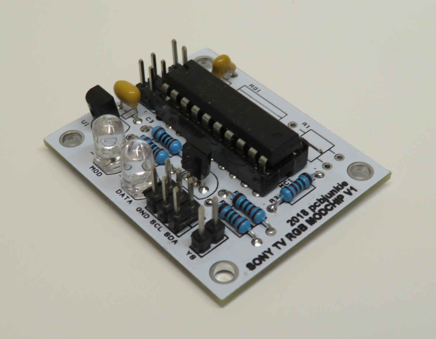
Here’s the pcb that I eventually developed for this purpose. All it is is a board that has the necessary headers for the I2C connections and power, voltage regulation for the MSP430, the microcontroller itself, a couple of LEDs and a transistor for changing the bits on the data line.
I made a couple of videos on the subject. The first attempt was successful with a Sony XBR-51.
The second attempt wasn’t, but I learned that different Sony Y/C Jungles don’t use the same I2C protocol.
The current solution is as follows. Use an MSP430 microcontroller, to read the I2C communication and look for the RGB port setting. When the setting bits are in frame, modify them accordingly.
Were’s looking for the register 0x88 and sub register 0x0C in which the last 2 bits (LSB) are the RGB setting. Here’s the relevant page from the datasheet.
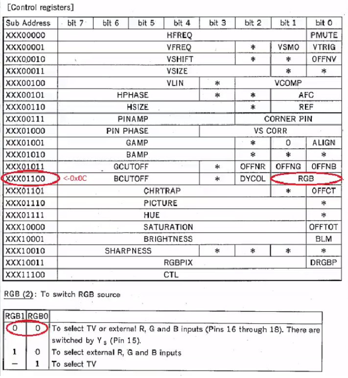
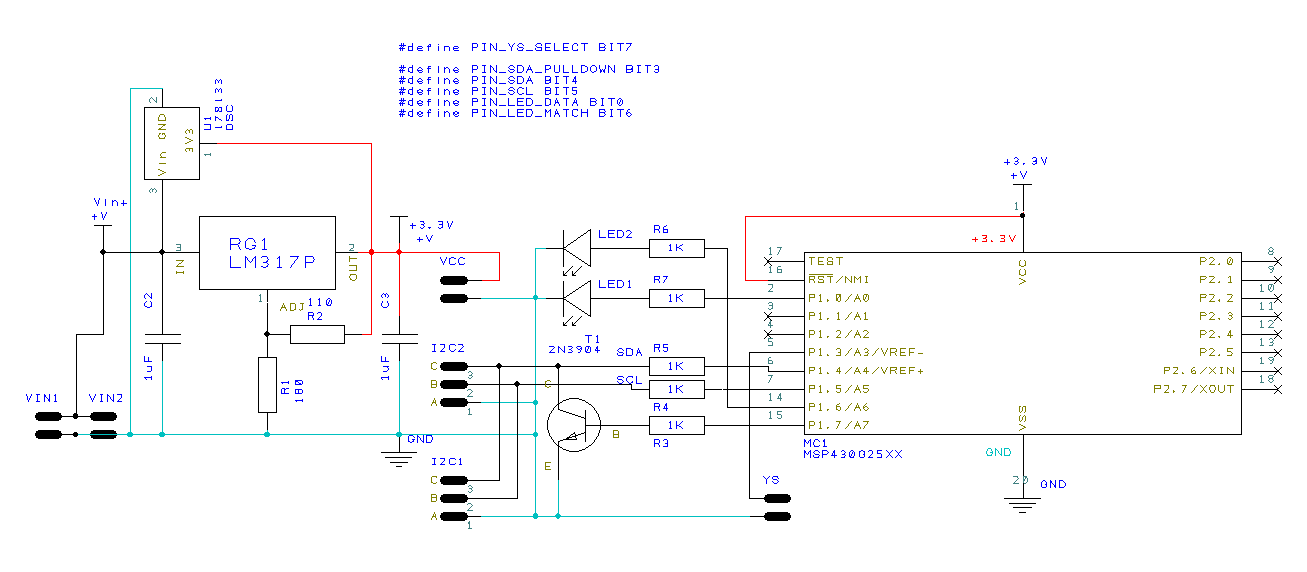
Here’s the schematic. Pin 1.7 of the MSP430 is used to pull down the bits of the I2C line down to a 0 for the relevant portion of the RGB register.
And here’s the code that makes this work:
// Freeware with no strings attached, witout warranty. Use at you own risk for whatever you want. // 2018 pcbjunkie.net // This code can be used in Sony CRT TVs to enable unused RGB inputs on YC jungle chips // that have these inputs normally disabled. The jungle chip normally receives the code: // 0x88 0x0C 0xC5 to disable RGB switching completely. // // 0x88 - YCJ receiver address. // 0x0C - BCUTOFF, DYCOL, RGB register. // 0xC5 - Typical value (may vary). Only last two LSB are of importance here. // // The RGB bits in the value 0xC5 // are the last 2 least significant bits, 0bCCCCXDAB where X=don't care and AB is // typically 01. CCCC is the blue CUTOFF value, and D is the DYCOL bit. // // The code for RGB switching is as follows: // // A B Mode // - - ----------------------------------- // 0 0 YS pin switches between TV and RGB // 1 0 Selects external RGB inputs. // X 1 Selects TV mode // The code will monitor the I2C communication to the YCJ chip and when the 0x88 0x0C // configuration code is detected, the last two bits of the following byte will be forced // low by pulling the SDA line low for two SCL cycles.// pins definition #define PIN_YS_SELECT BIT7 #define PIN_SDA_PULLDOWN BIT3 #define PIN_SDA BIT4 #define PIN_SCL BIT5 #define PIN_LED_DATA BIT0 #define PIN_LED_MATCH BIT6 // search and replace variables, look for this pattern unsigned const int match_pattern = 0x880c; // force low these bits following matched pattern (0 = force low, 1 = don't care) unsigned const char replace_pattern = 0b11111100; // I2C decoder variables const int STATE_START = 1; const int STATE_STOP = 2; volatile unsigned long wtdisrcount = 0; void init(void) { // slow clock init DCOCTL = 0x00; BCSCTL1 = 0x00; WDTCTL = WDTPW + WDTHOLD; // Stop WDT // set pulldown, and led pins as output P1DIR = PIN_SDA_PULLDOWN | PIN_LED_DATA | PIN_LED_MATCH; P1OUT &= ~PIN_LED_DATA; P1OUT &= ~PIN_LED_MATCH; __delay_cycles(500); // fastest clock now -- all bits set on DCO and RSEL, but no MOD DCOCTL = (DCO0 | DCO1 | DCO2); // DCOx = 7 BCSCTL1 = (RSEL0 | RSEL1 | RSEL2 | RSEL3); // RSELx = 15 // calibrated clock -- but we don't care about precision, just want the fastest possible // BCSCTL1 = CALBC1_16MHZ; // DCO range set to 16 MHz // DCOCTL = CALDCO_16MHZ; // DCO frequency set to 16 MHz } void main(void) { register unsigned int lastp1; register unsigned int thisp1; register int state; register unsigned int val; register unsigned int bitsleft; register int matched; register unsigned int pattern; init(); thisp1 = P1IN; lastp1 = thisp1; while(1){ // loopcnt++; lastp1 = thisp1; thisp1 = P1IN; // P1OUT ^= PIN_SDA_PULLDOWN; // look for a start condition, SDA falling edge while clock high if ((thisp1 & PIN_SCL) && (lastp1 & PIN_SDA) && !(thisp1 & PIN_SDA)){ state = STATE_START; val = 0; bitsleft = 8; matched = 0; P1OUT |= PIN_LED_DATA; P1OUT &= ~(PIN_LED_MATCH | PIN_SDA_PULLDOWN); } // if SCL rising edge while state = STATE_START, capture data else if (state == STATE_START){ // rising edge of clock if (!(lastp1 & PIN_SCL) && (thisp1 & PIN_SCL)) { if (bitsleft){ val = val << 1; if (thisp1 & PIN_SDA){ val = val | 1; } bitsleft--; } else{ bitsleft = 8; P1OUT &= ~PIN_SDA_PULLDOWN; if (val == match_pattern){ matched = 1; P1OUT |= PIN_LED_MATCH; pattern = replace_pattern; } else matched = 0; } } // falling edge of clock, do the pulldown here else if ((lastp1 & PIN_SCL) && !(thisp1 & PIN_SCL)) { if (matched && bitsleft){ if (!(pattern & 0b10000000)){ P1OUT |= PIN_SDA_PULLDOWN; // testing // P1DIR |= PIN_SDA; // P1OUT &= ~PIN_SDA; } pattern = pattern << 1; } else{ // pulldown off unless matching and patters agrees // P1DIR &= ~PIN_SDA; P1OUT &= ~PIN_SDA_PULLDOWN; // testing } } } // WDTCTL = WDTPW + WDTCNTCL; } }
Some links to other Sony datasheets are here.
I do have the board gerbers if anyone wants to give this a shot with their own TV. Contact me if you want to get a pcb from me.