
By far, the best thing about this adapter, is how little time it take to configure it for your game. The process could not be any easier.
There are two ends of the adapter. The JAMMA side that plugs into your cabinet, and the GAME side into which you plug your non-JAMMA game.
You don’t need to know anything about the JAMMA side, like for example which pin is responsible for which function. What you do need to know however, is what each pin on the GAME side is for. You can find this pinout information on various sites or just google for it.
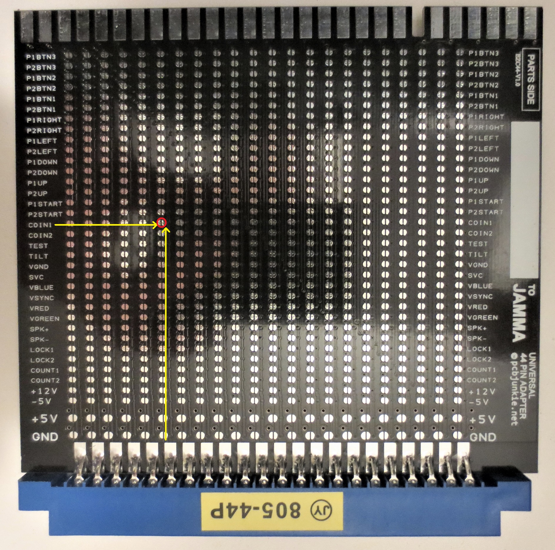
In order to hook up a game pin to a specific JAMMA function, physically locate the pin in question on the GAME end. Then, simply solder the jumper pad that lines up with the column where the pin resides, and the row that corresponds to the required JAMMA function.
The picture below illustrates how the 6th pin from the left can be wired to COIN1 on the JAMMA harness if the pad circled in red is jumpered.
Repeat this process for all the pins you want to map and you’re done!
If you notice, the game side pins are not labeled or numbered. This is because there are a number of ways manufacturers label the pins on the connector. Some are left to right, some are reversed. It will be up to you to figure out the physical location of the pin and its function.
As an example, let’s assume that you’re wiring up Pengo using the 44 pin universal adapter. The pinout information is as follows:
              COMPONENT  |  SOLDER
    -------------------------------------------
               GND   | 1 | A |   GND
               GND   | 2 | B |   GND
               +5V   | 3 | C |   +5V
               +5V   | 4 | D |   +5V
               +5V   | 5 | E |   +5V
      Coin Meter 2   | 6 | F |   1P.Button
      Coin Meter 1   | 7 | G |   2P.Button
            Coin 2   | 8 | H |   Coin 1
           Service   | 9 | I |   Test
          2P Start   |10 | J |   1P.Start
          1P.Right   |11 | K |   1P.Left
             2P.Up   |12 | L |   1P.Up
          2P.Right   |13 | M |   2P.Left
           1P.Down   |14 | N |
               GND   |15 | O |   GND
             Green   |16 | P |   Red
              Sync   |17 | Q |   Blue
           Speaker   |18 | R |   2P.Down
              +12V   |19 | S |   +12V
            Volume   |20 | T |   Volume
               GND   |21 | U |   GND
               GND   |22 | V |   GND
We can determine from looking at the game board, that the tree consecutive power pins for +5 V are on the right.
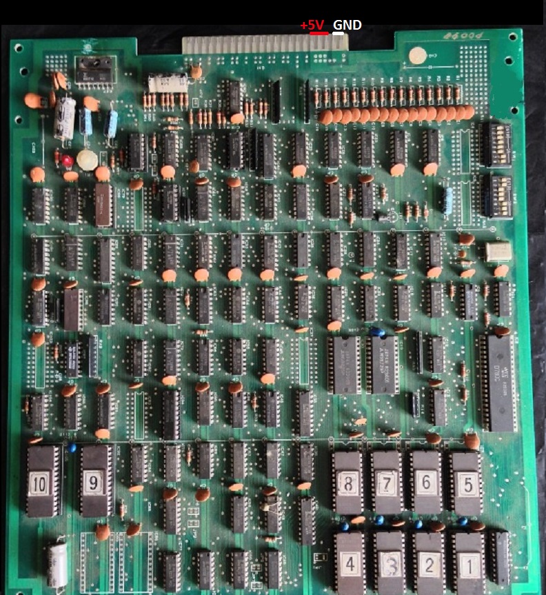
We can then confirm that the pinout is ordered right to left when looking at the parts side of the adapter board. We can now begin soldering the jumper pads.
The picture below shows the component-side pads that need to be soldered to wire up half of the adapter. From right to left, it will be GND, GND, +5V, +5V, +5V, COUNT1, COUNT2, COIN2, SVC, etc…
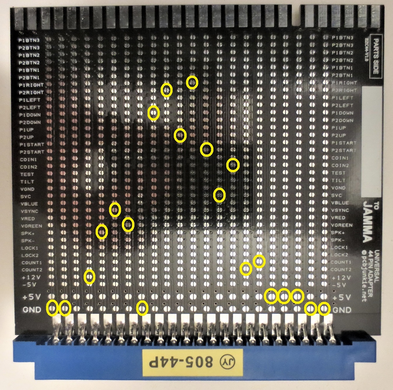
Once that’s done flip the adapter over and connect all the solder side pins in the same manner. Keep in mind that once flipped the pinout order will be reversed.
If you make a mistake, gently run the tip of the soldering iron across the jumper pad to break the connection, and try again. The pads can be cleaned up further with some wick. Be careful with the pads though, don’t use to much heat or pressure, and don’t try to scrape the solder off, as the pads may lift.
As you can see, it won’t take long at all to complete the process. Certainly it will be much faster than using other types of adapters.
When the soldering is done, you can use a permanent marker to label the adapter in the white rectangle provided specifically for that purpose.
I created 3 types of these adapters for games with different pin counts. These are 36 pin, 44 pin and 56 pin. Having three variants means there are fewer pads on the 44 and 36 pin adapters which makes the process easier. Those are also smaller and can carry more current due to the increased trace width.
As always, these adapters are available for purchase on my Ebay store here.