Here are some tips on how to assemble the Generic JAMMA Adapter to create the best possible end result.
Here are the assembly steps:
1. Ensure you are Using the Right Kit:
Check that the the edge connector is compatible with your arcade PCB and that is fits. You’d be surprised how often this gets overlooked. Initially the brand new connector may be difficult to connect without the additional leverage of the rest of the adapter.
2. Edge Connector Preparation:
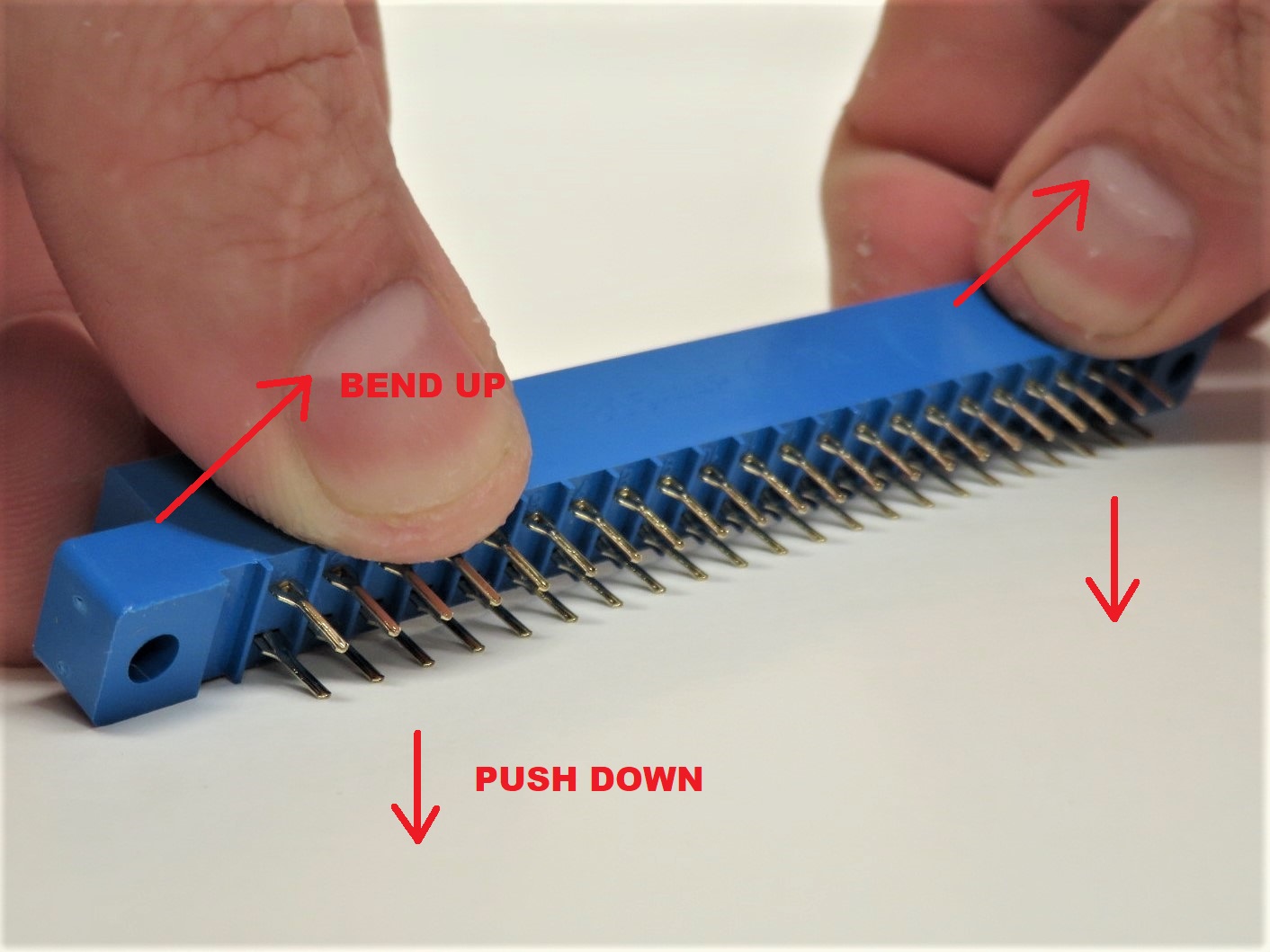
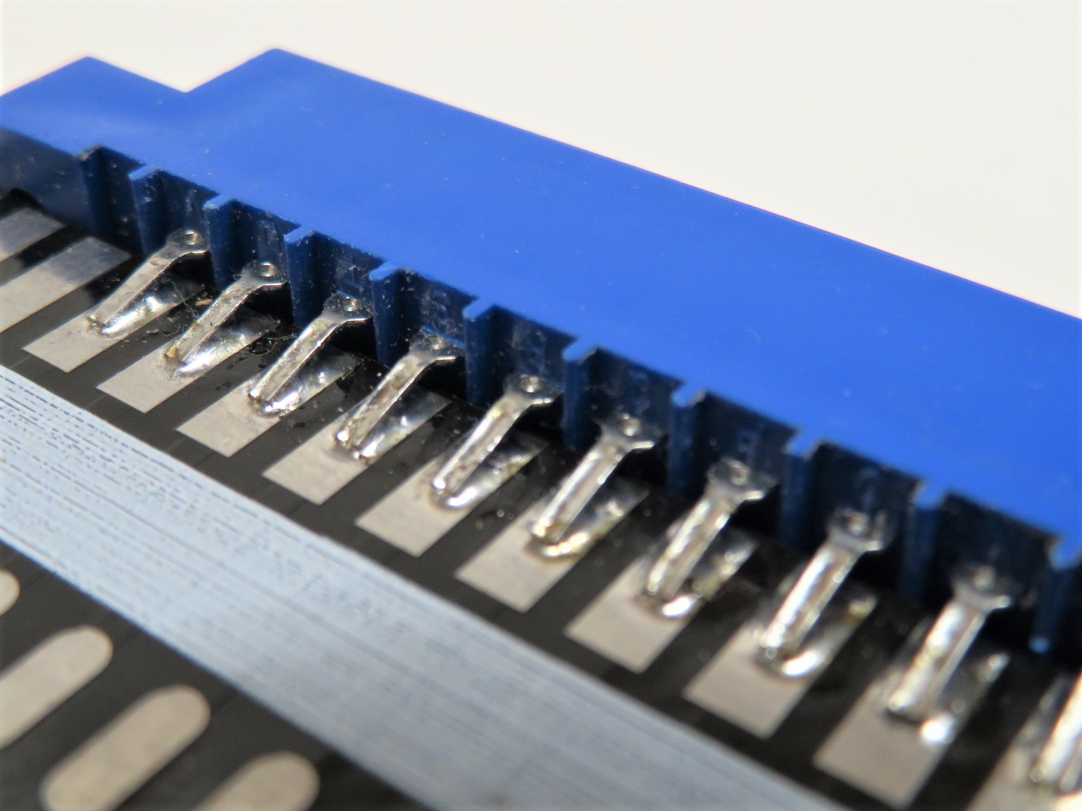
Prepare the Edge Connector before soldering it to the board by bending the pins inwards to minimize the solder used and create the best possible connection. You will want to use a hard, straight surface like glass or tile. Doing this on a soft surface like wood will scratch the surface and may not bend the pins uniformly across.
Place connector pins level on the surface and angle the plastic head up while pushing down on the pins. Do not push too hard as you may bend the pins too much and subsequently break them.
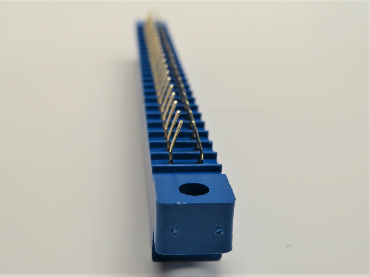
Flip the connector to the other side and do the same thing. Do not worry about the pins not touching, you’ll need to slide in the conversion board later. After you do this ensure that the angle of the bend is approximately the same on both sides of the connector.
3. Slide in the Conversion Board:
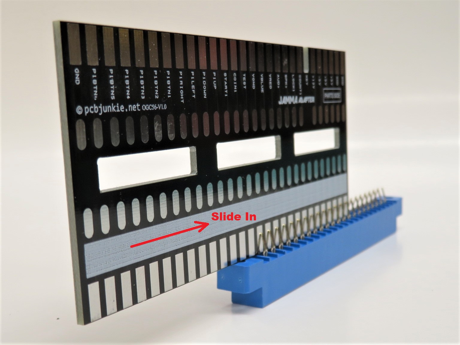
Slide in the board from one side and gently push it in all the way until the pins line up and the edge connector is centered. If you bent the pins correctly in the first step, there should be some resistance but not so much that the board wiggles around between the pins.
4. Solder the Connector to the Board:
You’ll want to have a level surface now, with something supporting the board so that it is parallel with the edge connector. Solder a couple of pins from each edge on both sides, and inspect that the board is still parallel. If not you can gently adjust the angle at this point.
Continue with the rest of the pins. Use the least possible solder while making sure that the bond is strong enough (you’ll have to eyeball this) and use the same method for all other pins for the best looking result.
5. Solder the Wires:
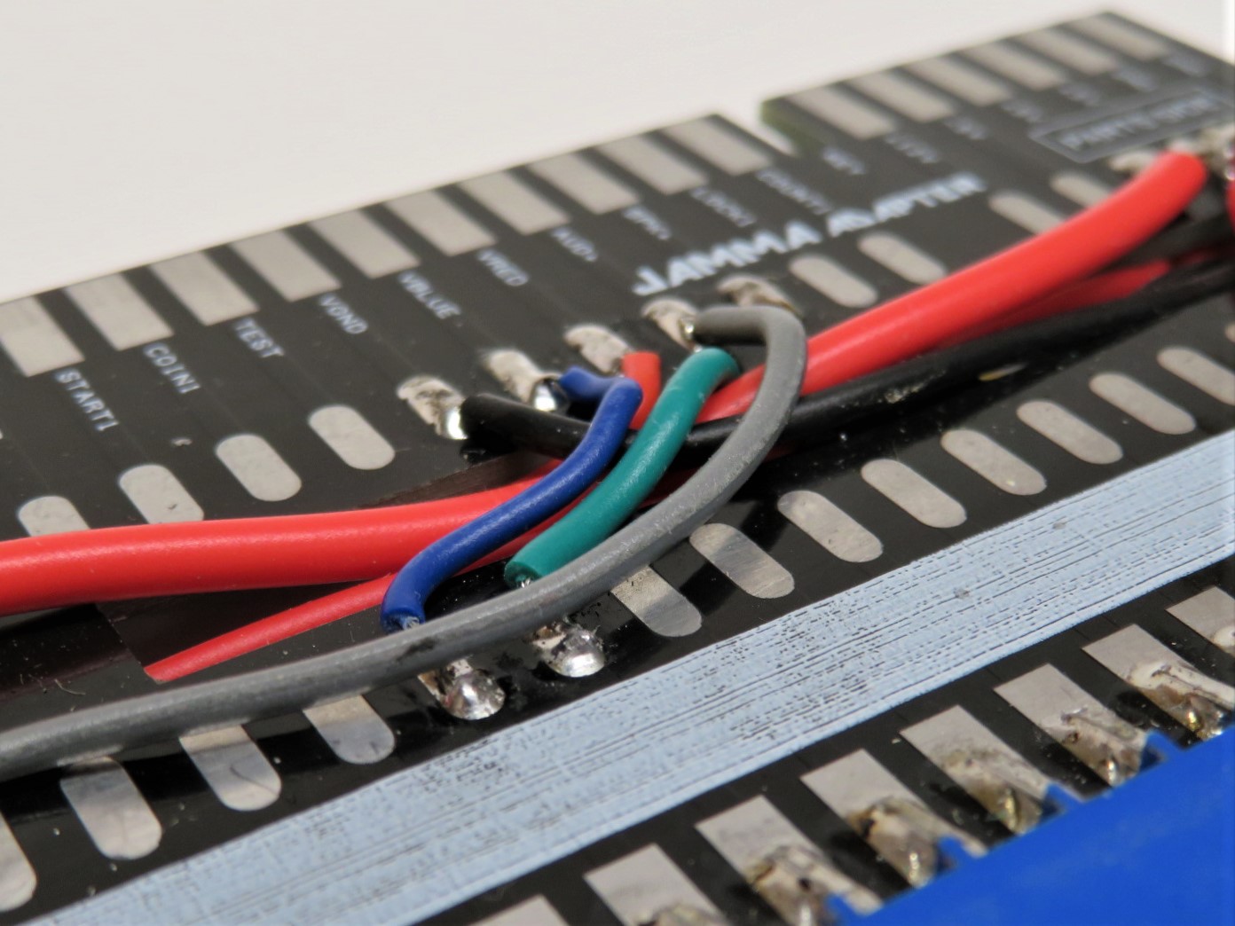
Use solid core wire if possible which stays firm and doesn’t move around much over time. The ideal wire thickness is 20AWG. You can use 18AWG for the power connections, and 22AWG for the controls. Use the shortest possible wire and lay it down flat on the board as much as possible. Avoid sharp bends, especially close to the solder points.
First, tread and solder the wires through the holes that map parts to solder side of the board, and use the shortest possible length. Continue with the other wires. Wires that make a connection across many pins of the board should run through the center of the adapter as much as possible. Finally, towards the end do the wires that map pins directly across from each other on the same side, and use those wires like a tie to hold the wires running through the center in place. This may require some pre-planning on your part.
6. Test and Enjoy:
Connect the adapter to the arcade board by sliding the edge connector onto the board on a bit of an angle. The initial connection may be tight but the connector will eventually wear in. Use a multi-meter in continuity mode to test the power from the JAMMA side of the adapter to known test points on the arcade PCB. Making sure the power is connected correctly is critical or you may cause damage to your PCB.